
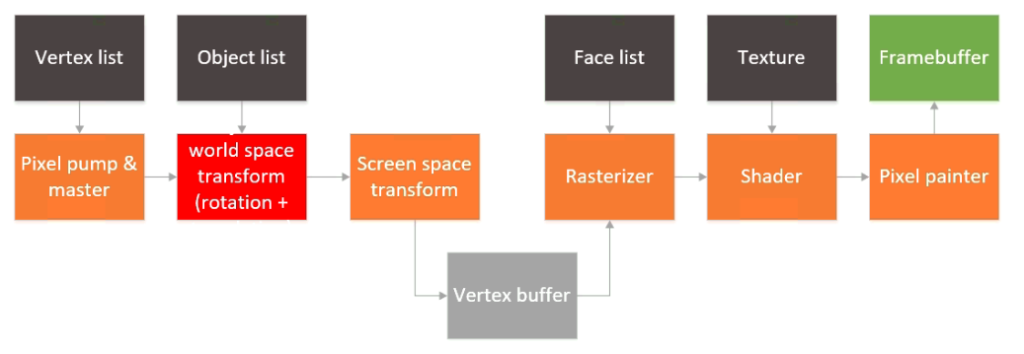
So, it’s been a long time since this project was started. Life has a strange was of getting in the way of hobbies, and sometimes we just can get enough time to finish things off. Thankfully, I had a chance a couple of weeks ago to finish off the last pieces I wanted to do and finally we have a real 3D rendered object on the screen, with real faces and even a simple texture. Last time this is how the architecture of the GPU looked like:
The rasterizer and shader were still not written or tested, and there was a camera space transform block missing in the pipeline as well. To speed up things a bit, I decided to drop the camera space transform block entirely. To be fair, that can be done in software and bundled into the word space transform + rotation block. That leaves two more blocks: the rasterizer and the shader.
For the rasterization process I tried several things, most of them ended up being bloated and/or not appropriate for implementation in an FGPA. I settled on finding out simply whether we were on the right side of the equations of three lines (the sides of the triangles). One of the rules I had when I started this project was that I would not look up other architectures or publicly available papers that would skew my design. It turns out that what I chose is pretty much what Juan Pineda proposed in 1988 in his paper “A Parallel Algorithm for Polygon Rasterization”.
The awesome thing of this algorithm is that (once optimized and after some solving some setup equations, the complexity boils down to tree sums per pixel, plus another thee sums per line:
// Scan through bounding rectangle
for (ap_uint<10> y = ymin; y < ymax; y++) {
	int cx1 = cy1;
	int cx2 = cy2;
	int cx3 = cy3;
	bool done = false;
	for (ap_uint<10> x = xmin; x < xmax; x++) {
                #pragma HLS PIPELINE II = 2 color_map_t a, b, c;
		barycentric(x, y, p1.x, p2.x, p3.x, p1.y, p2.y, p3.y, &a, &b, &c); if (cx1 > 0 && cx2 > 0 && cx3 > 0){
		output_pixel.depth = 1;
		output_pixel.u = a*u_a + b*u_b + c*u_c;
		output_pixel.v = a*v_a + b*v_b + c*v_c;
		output_pixel.x = x;
		output_pixel.y = y;
		raw_pixel_out << output_pixel;
	}
	cx1 -= dy12;
	cx2 -= dy23;
	cx3 -= dy31;
}
cy1 += dx12;
cy2 += dx23;
cy3 += dx31;
}
The code shown above is the HLS code of the heart of the rasterizer. As pixels are produced, their barycentric coordinates are also generated. This is used in the shader module. The shader itself has very simple code. It essentially just looks up the right address of the texture in DDR memory (using nearest neighbor interpolation) and uses that as the final color.
// Pump in
raw_pixel_in >> in;

// Basics
out.depth 	= in.depth;
out.x 		= in.x;
out.y 		= in.y;

// Generate address
uint32_t tex_x = in.u*255 & 0xFF;
uint32_t tex_y = in.v*255 & 0xFF;
uint32_t address = (tex_y)*256 + (tex_x);

//Get value
texture_pixel.col = texture_buffer[address];

// Color
local_color.chan.r = texture_pixel.chan.r;
local_color.chan.g = texture_pixel.chan.g;
local_color.chan.b = texture_pixel.chan.b;
local_color.chan.a = 255;
out.color 	= local_color.col;

// Pump out
cooked_pixel_out << out;
Nothing fancy, but looking up data in DDR involves an AXI4-Full master interface, so that ends up consuming a fair amount of logic anyway.
I wrote a little code to convert a bitmap to a C array and loaded in on the ARM processor. The processor initializes the array in DDR during boot up so things *should* just work as long as the texture coordinates are input correctly. This block diagram now looks like this:
Next up some render tests!