Finally a project came along that provided a nice excuse to take that PolySmooth filament out of its shiny metal foil pouch.
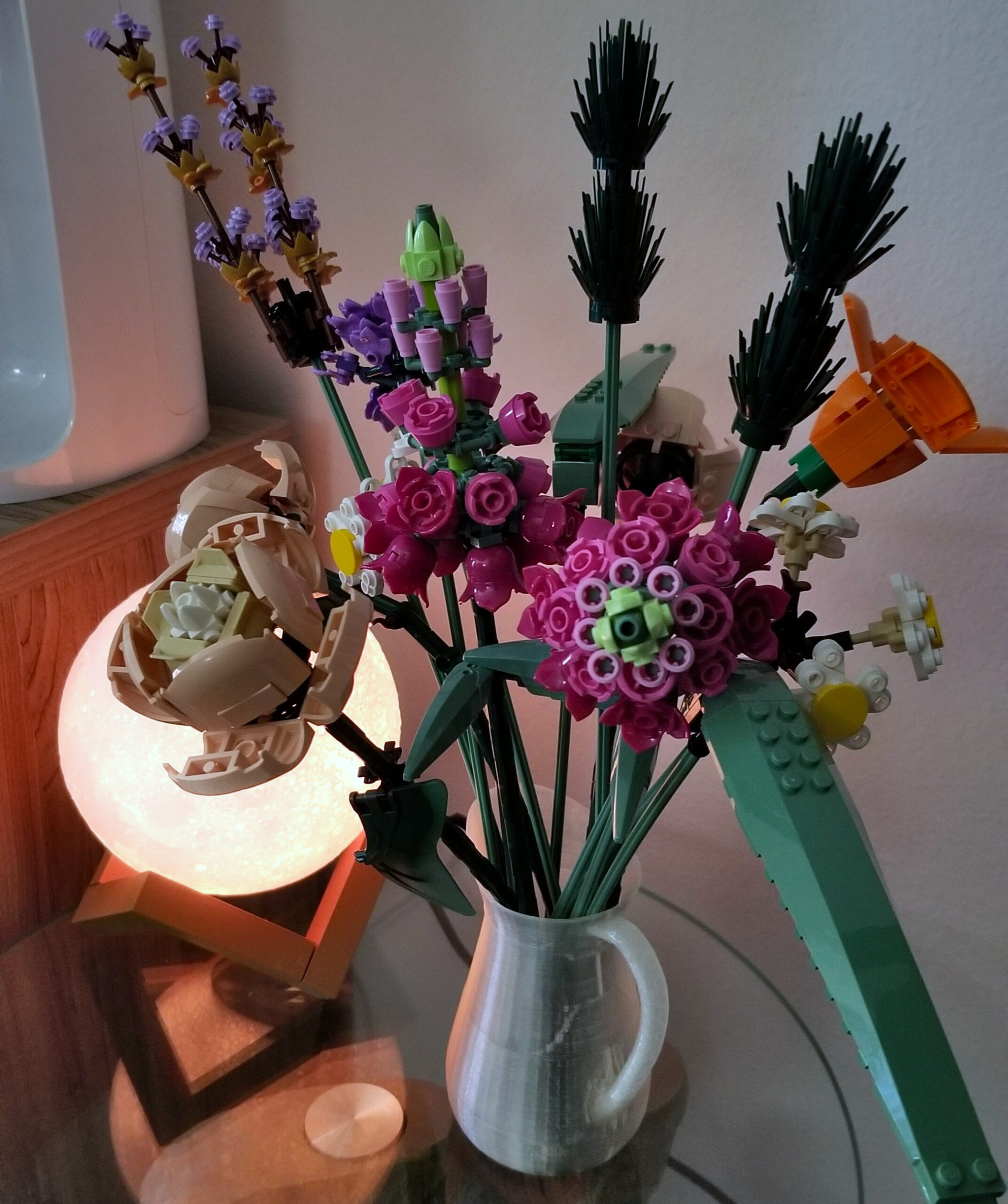
Recently got one of those really nice Lego Floral kits, and they had taken taken over the real flower vase at home. So we figured they needed their own vase. After a while searching, I found a very reasonable looking Milk Jug:
A few tweaks in blender to make the bottom flat, and thicken the walls to 0.8mm for printing. I didn’t go with Vase mode since the handle makes it not suitable for that mode.
5 hours later, and some processing to remove supports and it’s done. I ended up really liking the shimmery surface, so I didn’t use alcohol to polish the surface, but I’ll try a second print with single 0.6mm walls to try to get a smooth and hopefully fully transparent finish.
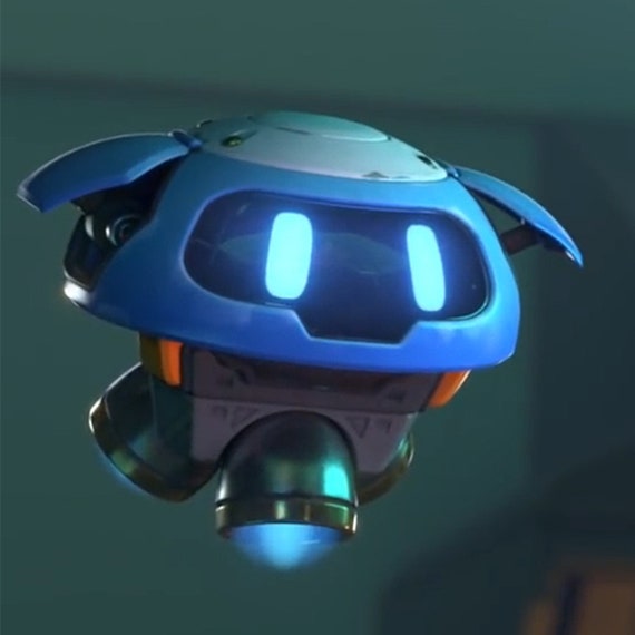
This is a project that has been going on for some time. I figured it was time to learn Blender since I longer have access to a 3D Studio Max license. What better way than by designing and printing all the parts of a functional little robot mascot!
This is the reference image I used. Basically tried to replicate the body shape and moving parts. The front face/mask was somehow really tricky to dial in to get the same feeling.
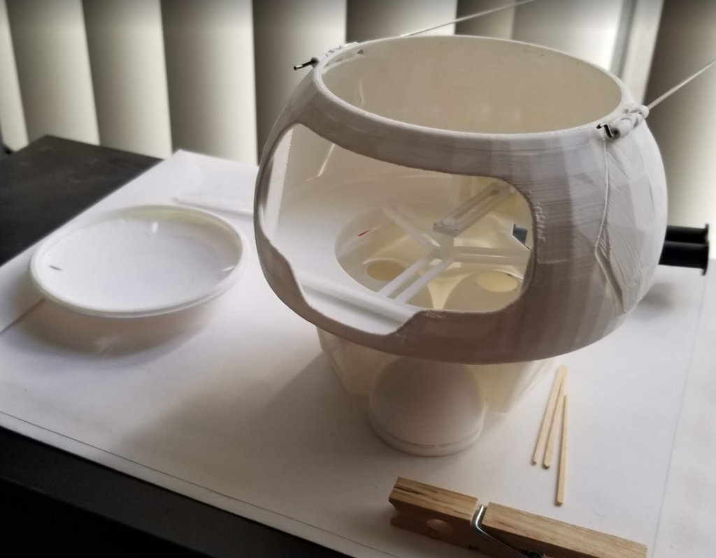
After designing the parts, I printed them on my Cetus 3D. This was lots of fun and I learned a lot about the limits of FFF printing.
I ran into problems with the hinges. Being the first 3d printed hinges I’ve ever created (and really just pushing through with blender), I made a lot of mistakes, so I ended having to use metal rods for some bits and more glue that I originally intended.
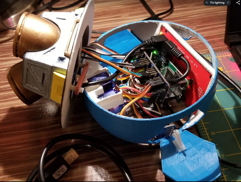
This stayed on a drawer for a while until I figured out how I was going wire all the internals. I used the following:
Raspberry Pi Zero W
TFT LCD
Adafruit mono audio AMP,
PWM expansion board
3 servos
3 RGB LEDs
USB Microphone
I’ve got some code up and running already to create some rudimentary facial expressions, servo motor control and RGB colors. I’ve also been experimenting with a few things to get voice recognition working.
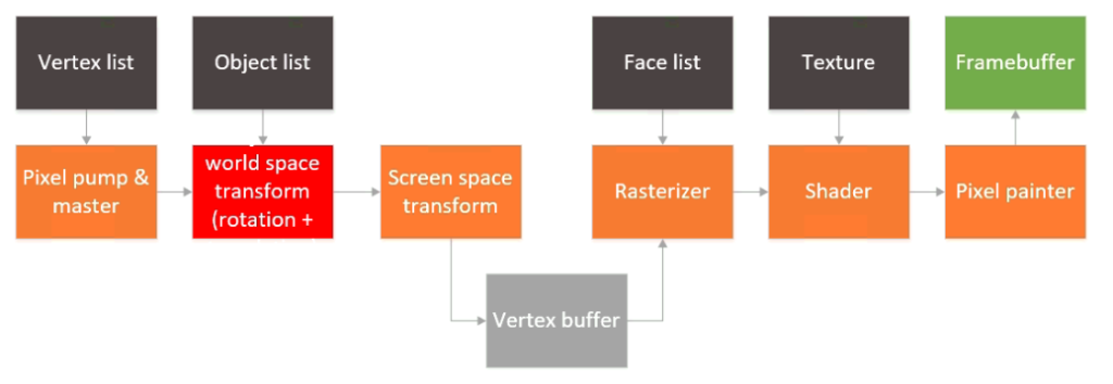
So, it’s been a long time since this project was started. Life has a strange was of getting in the way of hobbies, and sometimes we just can get enough time to finish things off. Thankfully, I had a chance a couple of weeks ago to finish off the last pieces I wanted to do and finally we have a real 3D rendered object on the screen, with real faces and even a simple texture. Last time this is how the architecture of the GPU looked like:
The rasterizer and shader were still not written or tested, and there was a camera space transform block missing in the pipeline as well. To speed up things a bit, I decided to drop the camera space transform block entirely. To be fair, that can be done in software and bundled into the word space transform + rotation block. That leaves two more blocks: the rasterizer and the shader.
For the rasterization process I tried several things, most of them ended up being bloated and/or not appropriate for implementation in an FGPA. I settled on finding out simply whether we were on the right side of the equations of three lines (the sides of the triangles). One of the rules I had when I started this project was that I would not look up other architectures or publicly available papers that would skew my design. It turns out that what I chose is pretty much what Juan Pineda proposed in 1988 in his paper “A Parallel Algorithm for Polygon Rasterization”.
The awesome thing of this algorithm is that (once optimized and after some solving some setup equations, the complexity boils down to tree sums per pixel, plus another thee sums per line:
// Scan through bounding rectangle
for (ap_uint<10> y = ymin; y < ymax; y++) {
	int cx1 = cy1;
	int cx2 = cy2;
	int cx3 = cy3;
	bool done = false;
	for (ap_uint<10> x = xmin; x < xmax; x++) {
                #pragma HLS PIPELINE II = 2 color_map_t a, b, c;
		barycentric(x, y, p1.x, p2.x, p3.x, p1.y, p2.y, p3.y, &a, &b, &c); if (cx1 > 0 && cx2 > 0 && cx3 > 0){
		output_pixel.depth = 1;
		output_pixel.u = a*u_a + b*u_b + c*u_c;
		output_pixel.v = a*v_a + b*v_b + c*v_c;
		output_pixel.x = x;
		output_pixel.y = y;
		raw_pixel_out << output_pixel;
	}
	cx1 -= dy12;
	cx2 -= dy23;
	cx3 -= dy31;
}
cy1 += dx12;
cy2 += dx23;
cy3 += dx31;
}
The code shown above is the HLS code of the heart of the rasterizer. As pixels are produced, their barycentric coordinates are also generated. This is used in the shader module. The shader itself has very simple code. It essentially just looks up the right address of the texture in DDR memory (using nearest neighbor interpolation) and uses that as the final color.
Nothing fancy, but looking up data in DDR involves an AXI4-Full master interface, so that ends up consuming a fair amount of logic anyway.
I wrote a little code to convert a bitmap to a C array and loaded in on the ARM processor. The processor initializes the array in DDR during boot up so things *should* just work as long as the texture coordinates are input correctly. This block diagram now looks like this:
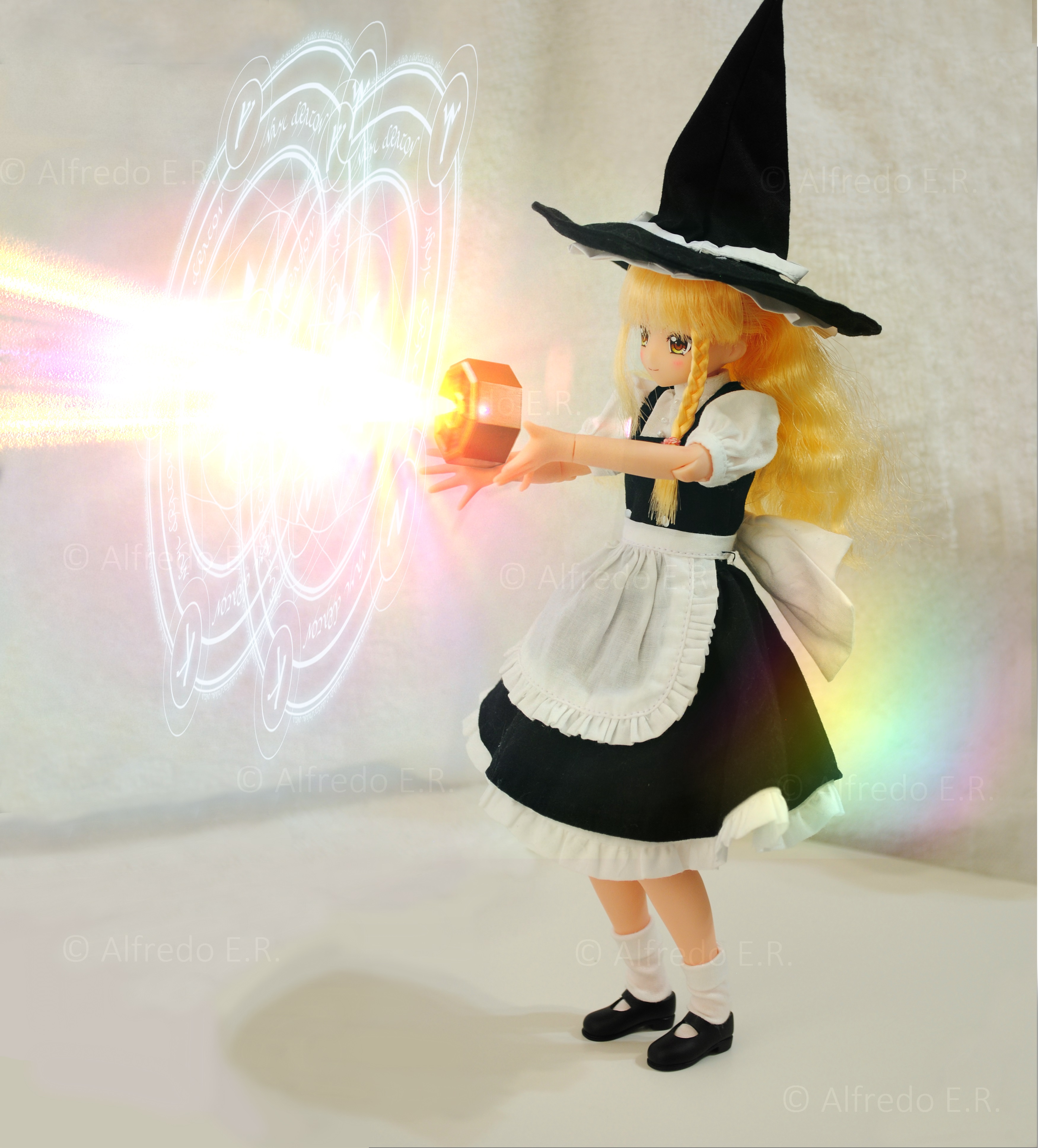
It’s been a while since I’ve last posted. Lots of things going on, got a new job, lots of training in FPGAs, got married and finally I am starting to have time to put into my hobbies again. After many years I was finally able to buy a Pure Neemo version of Marisa Kirisame. This scene took a while to take. First off, I had some trouble figuring out some settings on the camera, and after that Marisa did not want to use her mini hakkero. I ended up taking her broom and she got angry and scorched the wall.. I did manage to take this snapshot though.
Hope to revive the site a bit. I have three posts in the cook already. Cheers!
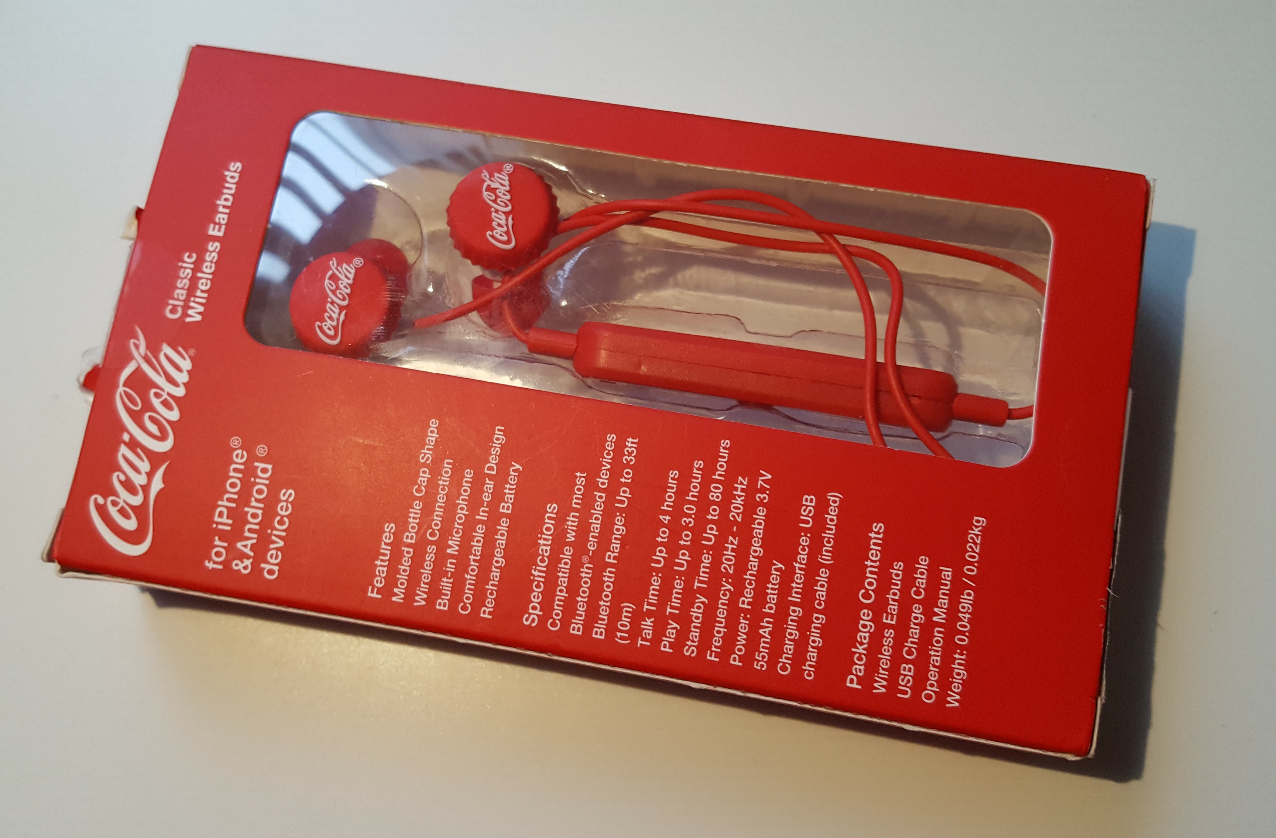
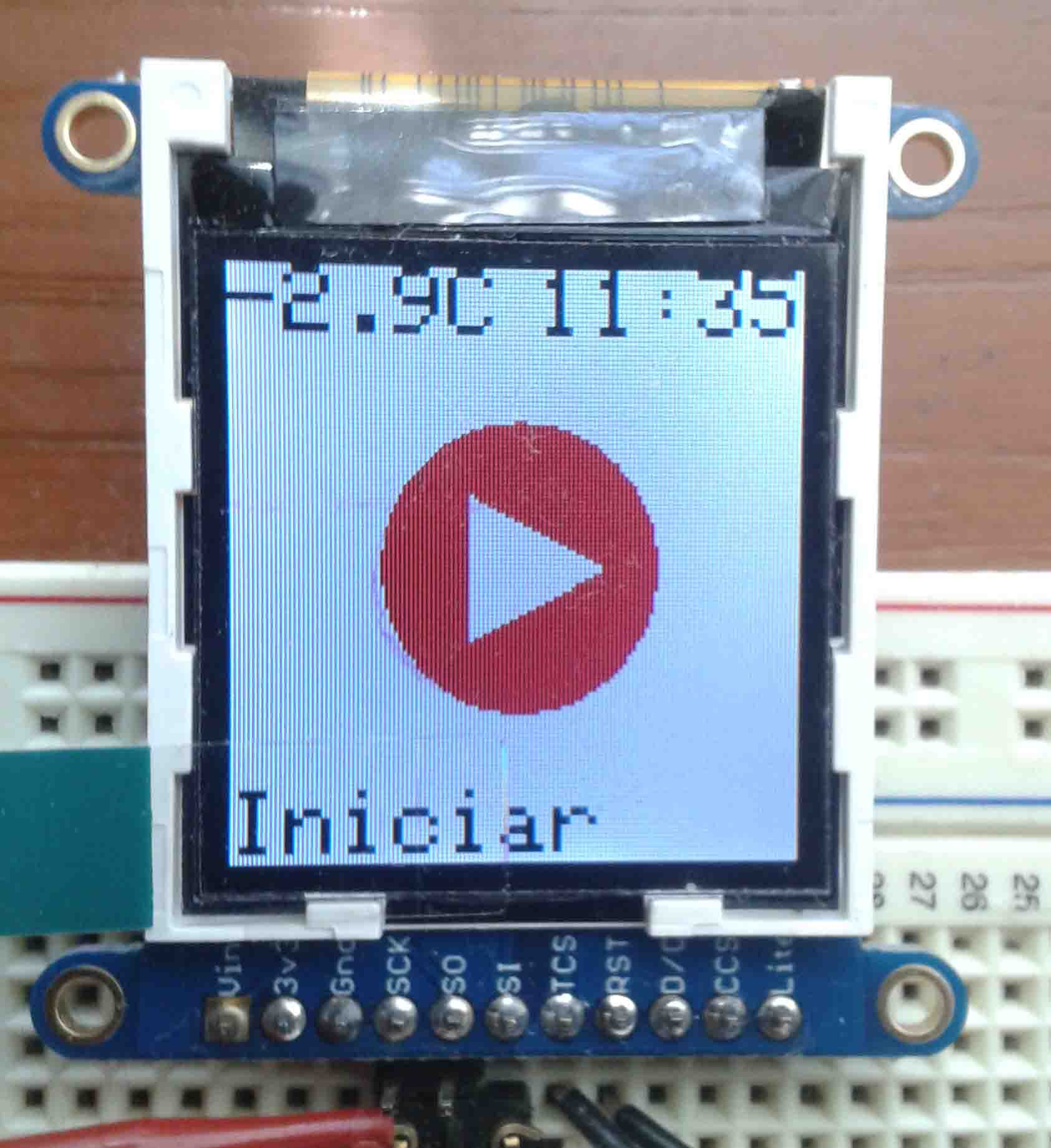
Continuing with the previous post, I’m sharing the black and white converter for the Adafruit 1.44″ TFT. This program converts any .PNG image into a constant char array that can be included and shown directly on screen. This program and accompanying code shows monochrome bitmaps (custom foreground and background colors) on the ST7735R driver. It was tested on a green tab TFT and is substantially much faster than the stock bitmap drawing routines.
After many delays, the migration is almost completed. I got a hold of a domain and transferred all the goodies over to my own host. Some things still need to be fixed, but hopefully during the week it will be done. I still need to cough up the dollars for the site-redirect feature in wordpress.com.
After having fiddled with my own website for some time, and having collections of projects in different places, I decided hereafter to start posting my projects in this blog. As much as I have liked the simplicity of Blogger, I can never feel that I get the right touch to the posts. And since I would like to share tutorials and repositories in the future, I think that wordpress gives the right flavour needed for these things. As a little history, I am an Electronics Engineer that loves to fiddle with microcontroller technologies, ASIC design, algorithms, math and Japanese pop culture. I hope you’ll enjoy reading through my posts as much as I will enjoy writing down these posts as a form of long term archive.