So, the time has finally arrived. Time to tackle the GPU in HW! So, a quick disclaimer: since this is a hobby project I will use HLS to quickly iterate designs and reach a functional RTL. All of the blocks will be designed considering that they are meant for RTL and (given enough time) could be replaced by hand coded VHDL/Verilog without too much hassle. This is the architecture that I am envisioning:
Category Archives: Microcontrollers
SHADE Sun Photometer Bootloader
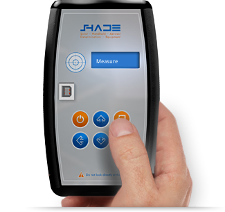
This post comes almost out of the blue, but in reality is the culmination of a long time of work. It is the final piece of software that was needed in one of the projects that I have spent the most time working on, the SHADE Sun Photometer. This is a handheld low cost instrument for measuring atmospheric aerosols that is intended to be used in aerosol measurement campaigns and as part of the GLOBE program, allowing kids and students to obtain measurements that are up to par with the data quality requirements that NASA scientists need, without having a huge price tag on it. Although we have been delayed many times, and have faced many difficulties in completing the instrument, it is one step closer to being ready for production. Here is the site that we have for it:
I would like to note that our intention in producing this instrument is to enable a global network of aerosol measurements, and collaborate in some way with the task of understanding and fighting climate change. We started this as a school project and have developed this with our spare time and budget, so lots of bugs are still present. Which brings me to the point of this post, a bootloader!
Adafruit image bitmap generator
This little project came out of the necessity for a program that could be used to generate embedded images for use in Adafruit TFT screens. This program converts any .PNG image into a constant char array that can be included and shown directly on screen. This program and accompanying code can show either packed color RGB 565 or monochrome bitmaps (custom foreground and background colors) on the ST7735R driver. These were tested on a 1.44″ Color TFT LCD Display and are substantially much faster than the stock bitmap drawing routines.
Tutorial: Switching clock modes with the FRDM KL25z in mbed
Ever since I got a hold of my FRDM-KL25Z board I fell in love with it. It has the convience of running straight from either the built in SDA USB connector, an external 5-9 volts supply or a regulated 3.3v supply. It boasts USB host, ultra low power modes, and when paired with the mbed online compilation polatform it essentially erased all my worries about working in several computers and file revisions. Once you use the mercurial based repository you will wonder why you ever did any project differently before. And it costs around 15.00 USD, so its a hard price break to beat for homegrown projects.
That being said, there are several disadvantages. Since you have to rely on the mbed library for mostly everything, some rather crucial functions are still not implemented, or probably fall outside the scope of the core mbed library. One of such functions is clock control. On the KL25z there is simply no way of switching the clock mode either than manually coding it. In this tutorial I will go through the steps of controlling the Multipurpose Clock Generator (MCG), or you can just skip the tutorial and get the library:
Microcontroller Mapper
This is little project that I worked on for a while. Imagine something like processor expert, but for Texas Instruments MSP430 (or most any family of microcontrollers). Its a GUI that allows you to quickly assemble a board definitions include file for use in your project with great ease, and writing the least amount of code by hand (which can be error prone if the project is quite large). I developed this tool after working on a projects that had to be ported to work from one microcontroller to lots of others. Instead of going around writing hundreds of lines of register #defines, I made a program that allows you to quickly assign pins and modules in microcontrollers, while simultaneously verifying that you did not map a pin twice in different functions.
Concept
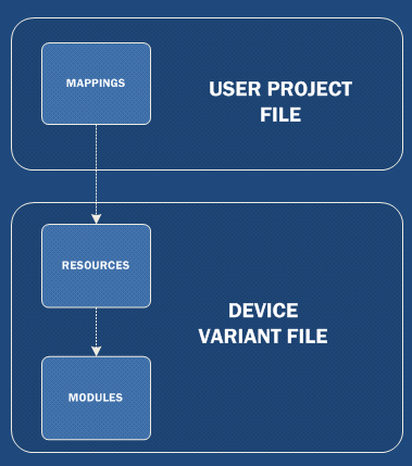
The mapping of the microcontroller is divided into three layers. Modules, Resources and Mapping.
- Modules are generic macro definitions that descrive microcontroller peripherals. These are generic, and can be reused as many times as copies of the hardware exist inside the microncontroller. For example a DIGITAL_PIN, or a UART.
- Resources are lists of modules that are given specific locations in a microcontroller. For example, P1.1 and P1.2 as a DIGITAL_PIN.
- Mapping involves connecting the users project to specific resources in a microcontroller. This translates to giving the resource macro a user friendly name in the location specified by the resource. For example, BUTTON1 in P1.1 (which will automatically get set as a DIGITAL_PIN).


