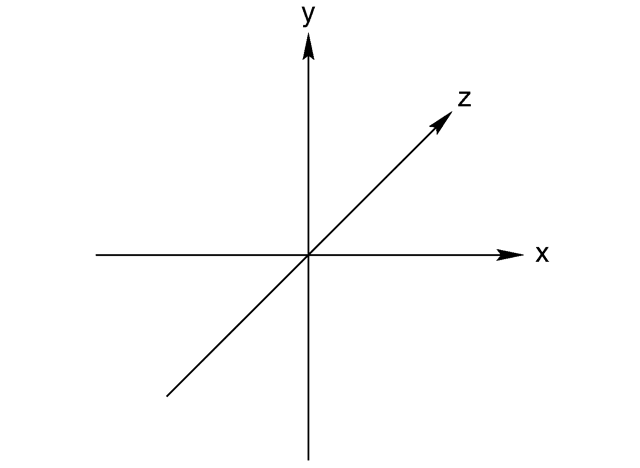
So, now that we have a way of showing images, let start digging into how we will actually generate the images that we will show. The basic idea is that a 3D scene is formed by a digital representation of the objects that we want to show, and that a video card transforms this information into a 2d image that we can see on a screen. The first side is usually the task of really 3d designers, game creators, artists and whismy programmers that create collections of points, lights and textures that represent a 3d object. Since we are starting from scratch, we will start by trying to render a collection of points in space. These points will simply be a set of (x,y,z) points in the world. I always like to use coordinates the way PC game designers use them:
GPU Project 02 – Basic frame buffer and DMA code
The idea in the previous post was to create a suitable framebuffer display circuit that could be used as a generic part of the video card that sends the content of the framebuffer to a monitor or tv. After I moved to a different computer I realized how inconvenient it is to have a project slaved to a particular set of board files. These are not copied with the project so I decided to remove the dependency with the board files and synthesize again. (The updated Vivado project and bitstream are attached).
So, with the FPGA fabric in place we needed to create a basic application that runs on the Zynq’s ARM to write to the framebuffer and configure the VDMA block. This will work to verify that the output VDMA and VGA circuit is working correctly.
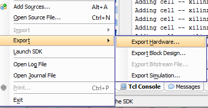
So, first thing first. We need to get a bare metal application working on the board. I exported the .HDF file from the Vivado project and fired up Xilinx SDK.
Random – CocaCola wireless headphones
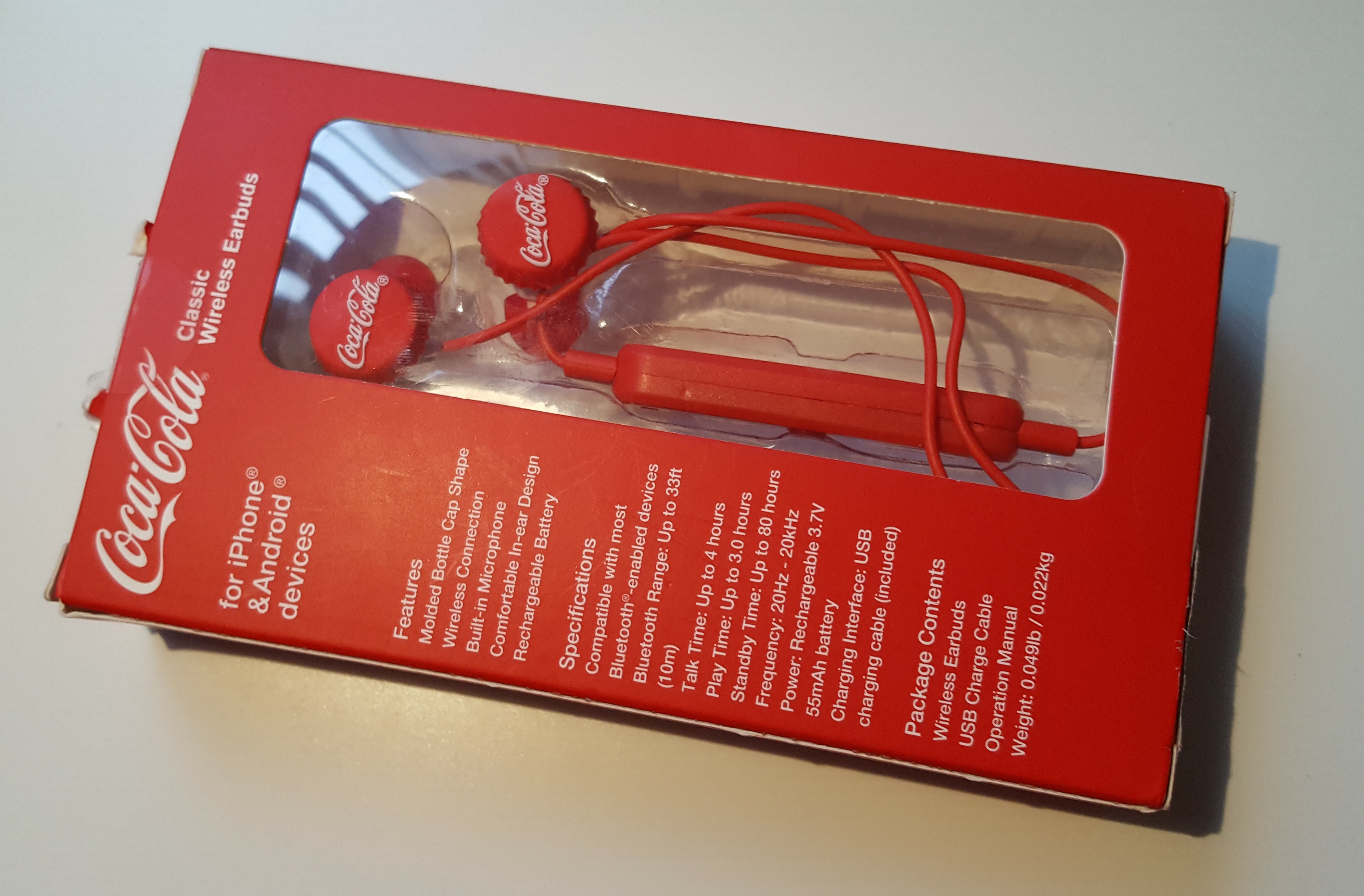
Completely random post, but had to share these CocaCola wireles earbuds that I found at a Tillys store yesterday. This is how they came in the box:
GPU Project 01 – Zybo is in!
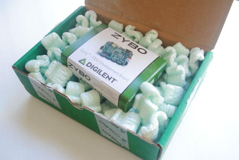
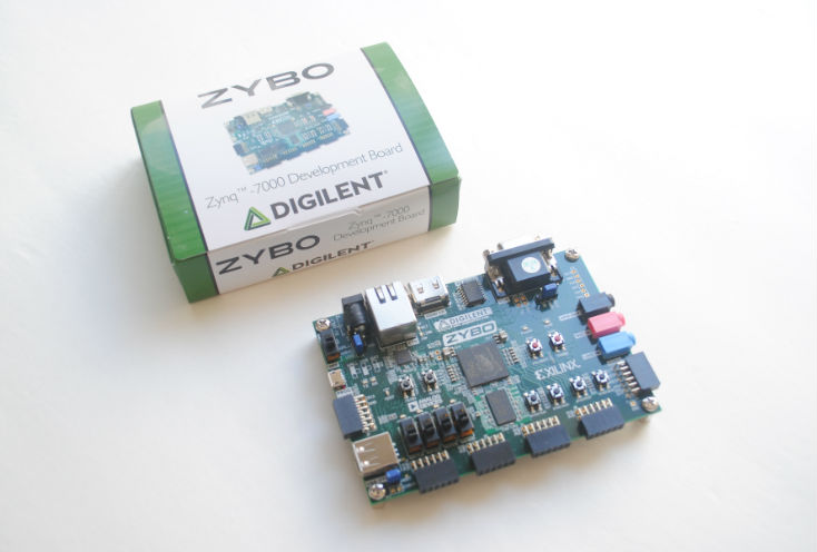
So, after waiting anxiously for a few days, it’s finally in. The box it arrived in was rather large, but really light. I was worried that there was nothing in it: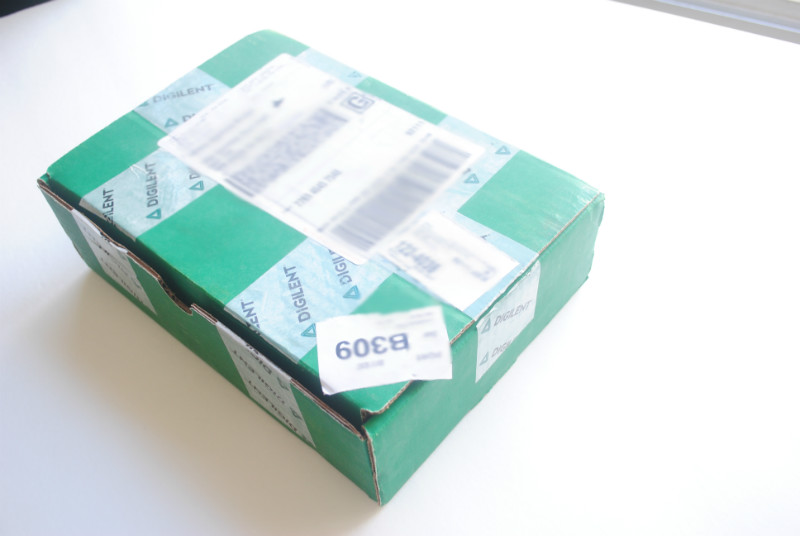
After opening it up, I can see that the real board is inside a much smaller box:
And finally taking out of the box:
So, time to roll up our sleeves! I installed Vivado 2016.2 with the free Webpack edition. Compared to the normal System Design edition it is mostly the same, but restricted to only a few devices. Thankfully for me, this Zybo board is one of the free devices supported by the free edition.
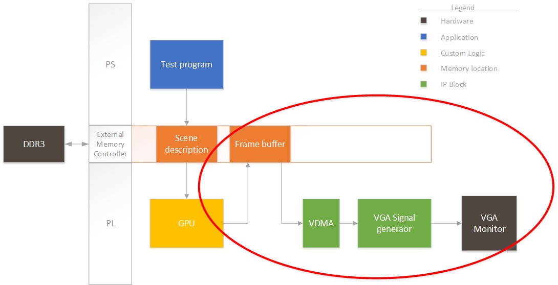
So, first thing first. I need to start creating a project that pumps out an image from a buffer in DDR to a display. Remember the block diagram from last post? We’ll focus on this for now:
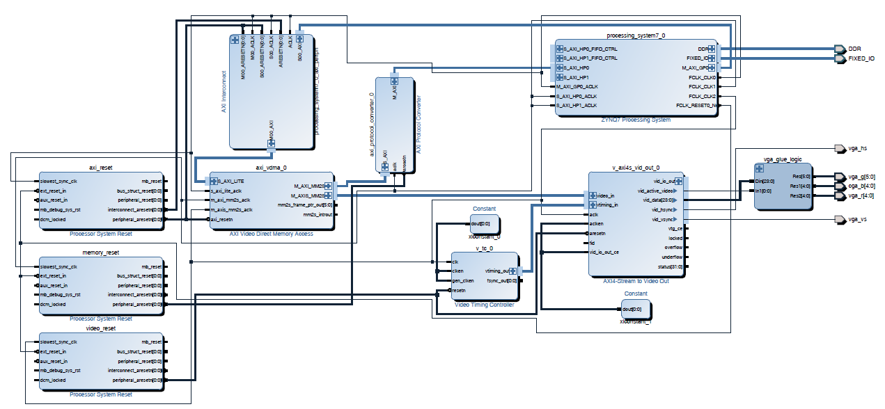
Right now we won’t have any fancy GPU rendering the image, so I’ll have the ARM on the Zynq draw some pixels to see that it’s working properly. So, for this design, I instantiate the PS section in Vivado and add three clocks to the system:
- AXI clock. I will use this for all the AXI-Lite interfaces to control registers, etc.I set this to 50MHz. Could be slower, but seems like a good starting value.
- Memory clock. I will use this to connect all the VDMAs and interfaces that need to talk to memory. I set this to 166MHz. Don’t ask why, but this always seems to work in all my designs.
- Video clock. This will be the pixel clock. Video interfaces will be connected at this speed. (40MHz). I chose this speed since I will be generating an output VESA 800×600 image stream at 60fps.
After adding in the clocks (generated by the PS section for simplicity), I also added a VDMA. This needs to be connected through an AXI protocol converter, since the PS block only supports AXI3, but everything else is AXI4. This first VDMA will pull data from the framebuffer into the logic. I then connected the VDMA to an output AXI to video out block. This block can directly drive a VGA port. The output video block requires some timing, so we also add a timing generator. The timing generator will run in master mode, clocking video for an 800×600 resolution.
Click on the image to expand it in case (most likely) things are squished in the browser. I will be posting the source files at the end of all my posts.
I added the constraints from the master XDC file on the Digilent website for the VGA port only. The next step is to run full synthesis/route/bitstream generation and see if we have something that is not broken. If that’s good then we’ll program the FPGA and start working on the ARM code that will configure the VDMA and write a test frame. Note that I’m uploading the design files as I’m working so things might be broken.
Goodies:
Time to run synthesis, see you next time!
GPU Project – Beginning!
So, after quite some I’ve finally started work on a project that I’ve wanted to do for a long time. I will start working on the architecture for a very simple GPU. The posts that I will be uploading will be both a collection of learning experiences as well as code for anyone that wants to replicate the effort.
Pure Neemo Hakurei Reimu
So, after waiting a long time for her to come along, I finally have the set of Reimu and Marissa together. Took a while to assemble her and get her hair bow in the right place, but here goes:
SHADE Sun Photometer Bootloader
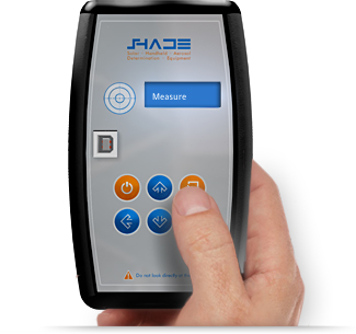
This post comes almost out of the blue, but in reality is the culmination of a long time of work. It is the final piece of software that was needed in one of the projects that I have spent the most time working on, the SHADE Sun Photometer. This is a handheld low cost instrument for measuring atmospheric aerosols that is intended to be used in aerosol measurement campaigns and as part of the GLOBE program, allowing kids and students to obtain measurements that are up to par with the data quality requirements that NASA scientists need, without having a huge price tag on it. Although we have been delayed many times, and have faced many difficulties in completing the instrument, it is one step closer to being ready for production. Here is the site that we have for it:
I would like to note that our intention in producing this instrument is to enable a global network of aerosol measurements, and collaborate in some way with the task of understanding and fighting climate change. We started this as a school project and have developed this with our spare time and budget, so lots of bugs are still present. Which brings me to the point of this post, a bootloader!
Pure Neemo Marisa Kirisame
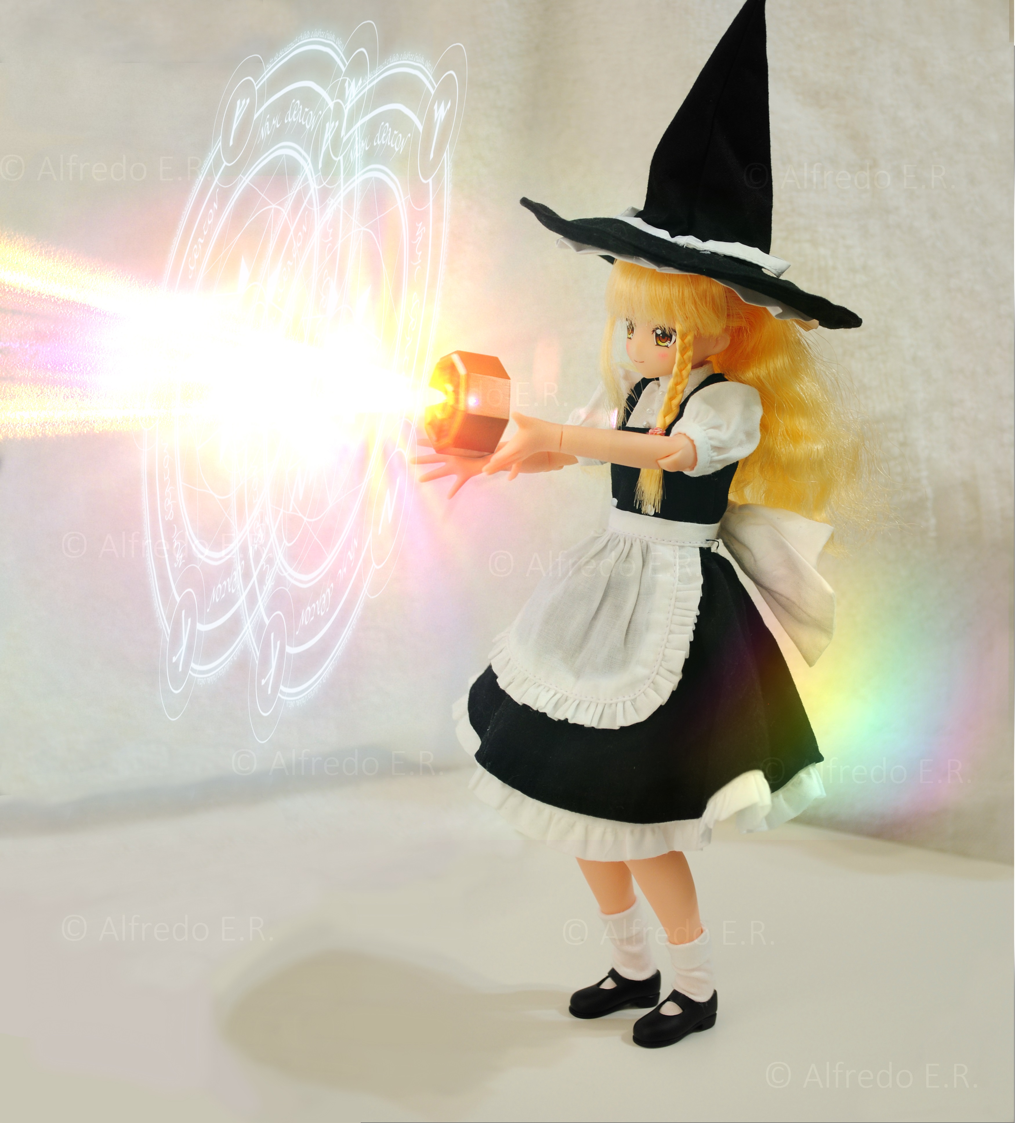
It’s been a while since I’ve last posted. Lots of things going on, got a new job, lots of training in FPGAs, got married and finally I am starting to have time to put into my hobbies again. After many years I was finally able to buy a Pure Neemo version of Marisa Kirisame. This scene took a while to take. First off, I had some trouble figuring out some settings on the camera, and after that Marisa did not want to use her mini hakkero. I ended up taking her broom and she got angry and scorched the wall.. I did manage to take this snapshot though.
Hope to revive the site a bit. I have three posts in the cook already. Cheers!
Adafruit monochrome image converter
Continuing with the previous post, I’m sharing the black and white converter for the Adafruit 1.44″ TFT. This program converts any .PNG image into a constant char array that can be included and shown directly on screen. This program and accompanying code shows monochrome bitmaps (custom foreground and background colors) on the ST7735R driver. It was tested on a green tab TFT and is substantially much faster than the stock bitmap drawing routines.
Adafruit image bitmap generator
This little project came out of the necessity for a program that could be used to generate embedded images for use in Adafruit TFT screens. This program converts any .PNG image into a constant char array that can be included and shown directly on screen. This program and accompanying code can show either packed color RGB 565 or monochrome bitmaps (custom foreground and background colors) on the ST7735R driver. These were tested on a 1.44″ Color TFT LCD Display and are substantially much faster than the stock bitmap drawing routines.

